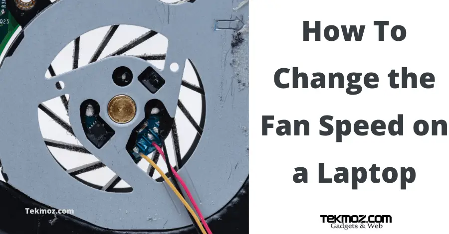

Also from the sensor wire you need to connect a 10k resistor to the Arduino's 5V pin. Then from it connect a jumper wire to Arduino Digital Pin 2. First you need to run the Signal wire (almost always yellow) to the breadboard. In our case we are going to use this to tell the Arduino how fast the fan is spinning. In fact you can plug the signal wire to the CPU fan header on a motherboard and set the BIOS so that if the fan ever stops sending a signal it will shut your PC down to prevent a CPU failure due to heat. While a nice feature for safety, it will be much cooler to see the RPM at which your fan is running than knowing your CPU wont melt if it dies right? This signal can be used to tell fan controllers or motherboard inputs how fast the fan's blade is tunring. The PC fan I have selected outputs RPM signals on its yellow wire. All we have to do is use the arduino to do is count that data, do some math for us, and output the converted data onto an LCD Screen.

This is accomplished by counting the falling edge of the square wave generated by the Hall effect sensor that is located inside the fan or pump. This also works well for the Water Pumps used in PC Water Cooling as well as any dc pump or fan that has a rotation sense wire. Today we are going to learn how to read the RPM of a PC Fan.


 0 kommentar(er)
